The function of the PCI slot is to allow you expand computer capabilities. PCI stands for Peripheral Component Interconnect. This is a computer slot that allows you to insert expansion cards into your computer. These can come in the form of sound cards, RAID cards, SSDs, graphics cards, NIC cards, Co-processors, and several other functional computer parts. So it enables you to expand the capabilities of the PC by adding what you do not have. It falls under the expansion bus category also known as the I/O bus. Other names for the I/O apart from expansion bus include, “external bus” or “host bus”.
An expansion bus is an input/output pathway from the CPU to peripheral devices. It is made up of a series of slots on the motherboard. Expansion boards (cards) plug into the bus. PCI is the most common expansion bus in a PC and other hardware platforms. Buses carry signals such as data, memory addresses, power, and control signals from component to component.
Expansion buses enhance the PC’s capabilities by allowing users to add missing features in their computers by slotting adapter cards into expansion slots.
An example of a network interface card that can be inserted into a PCI slot
PCMCIA – Personal Computer Memory Card Industry Association (Also called PC bus)
AGP – Accelerated Graphics Port
SCSI – Small Computer Systems Interface.
More About Function of PCI Slot
A PCI slot is a built-in slot on a device. It allows for the attachment of various hardware components such as network cards, modems, sound cards, disk controllers and other peripherals. It helped people with do-it-yourself (DIY) projects achieve their goals.
Intel designed and introduced this expansion bus architecture in 1992. Many early 1990s to the mid-2000s PCs had room for two to five PCI cards. Each card required an open slot on the motherboard and a removable panel on the back of the system unit. Adding PCI cards was an easy way to upgrade a computer since you could add a better video card, faster wired or wireless networking, or even adding new ports, like USB 2.0. It was also a sure way of replacing a faulty inbuilt card.
The first original 32-bit, 33 MHz PCI standard supported data transfer rates of 133 megabytes per second. An upgraded 64-bit, 66 MHz standard was introduced later and allowed for much faster data transfer rates up to 533 MHz. IBM, HP, and Compaq introduced PCI-X (or “PCI eXtended”), in 1998. This standard was backwards compatible with PCI. The 133 MHz PCI-X interface supported data transfer rates up to 1064 MHz.
Both PCI and PCI-X were superseded by PCI Express. It was was introduced in the year 2004.
PCI Express
PCI Express (Peripheral Component Interconnect Express), officially abbreviated as PCIe or PCI-e. It is a high-speed serial computer expansion bus standard, designed to replace the older PCI, PCI-X and AGP bus standards. It is the common motherboard interface for graphics cards, hard drives, SSDs, Wi-Fi and Ethernet hardware connections on personal computers.
Various slots on a computer motherboard, from top to bottom: PCI Express x4 PCI Express x16 PCI Express x1 PCI Express x16 Conventional PCI (32-bit, 5 V). Source: Wikipendia
Improvements Over Older Standards
Some of the improvements over the older standards are;
Higher maximum system bus throughput
Lower I/O pin count and smaller physical footprint
Better performance scaling for bus devices
Detailed error detection and reporting mechanism (Advanced Error Reporting, AER),
Native hot-swap functionality.
Recent revisions of the PCIe standard providing hardware support for I/O virtualization.
A computer bus is a common pathway through which information is connected from one component to another. Computers comprise many internal and external components. For these components to communicate with each other, a bus is used. This pathway is used for communication and can be established between two or more computer components.
In simple words, a computer bus is a set of parallel conductors, which may be conventional wires, copper tracks on a Printed Circuit Board, or microscopic aluminium trails on the surface of a silicon chip.
Data sharing– buses are designed to transfer
data between the computer and the peripherals connected to it. The data is
transferred in parallel, which allows the exchange of 1, 2, 4 or even 8 bytes
of data at a time. (A byte is a group of bits used to represent a character
normally 8 bits.) Buses are classified on how many bits they can move at the
same time, which means that we have 8-bit, 16-bit 32-bit or even 64-bit buses.
Addressing– A bus has address lines,
which match those of the processor. This allows data to be sent to or from
specific memory locations.
Power– A bus supplies power to various
peripherals that are connected to it. This is unlike a disk drive that needs to
be connected to the power supply unit.
Timing– The bus provides a system clock
signal to synchronize the peripherals attached to it with the rest of the
system.
Types of Computer Bus
A modern-day computer system can
be viewed as comprising just two types of buses. These are the System Bus and
the I/O Bus or Expansion Bus.
System Bus
The system bus is a pathway composed of cables and connectors used to carry data between a computer microprocessor and the main memory. The bus combines the functions of a data bus to carry information an address bus to determine where it should be sent, and a control bus to determine its operation.
By combining the three functions, manufacturers were able to reduce costs and improve modularity. Other names of the system bus are the internal bus, internal data bus, memory bus, or Front-Side-Bus.
The design of the system bus varies from computer to computer. Sometimes depending on the manufacturer it can be specific to a particular computer design or may be based on an industry standard. Using the industry standard makes it easy to upgrade the computer using standard components such as the memory and IO devices from independent manufacturers.
The size of the system bus, also
known as its width, determines how much data can be transferred at a time and
indicates the number of available wires. A 32-bit bus, for example, refers to
32 parallel wires or connectors that can simultaneously transmit 32 bits. A bit (short
for binary digit) is the smallest unit of data in a computer. It has a single
binary value, either 0 or 1.
I/O Bus or Expansion Bus
Short for input/output (pronounced “eye-oh”). This is a bus made up of electronic pathways that connect the different external devices, such as a printer, storage, monitors, keyboard, mouse, etc.
Thus I/O bus connects various peripheral devices to the CPU – these are connected to the system bus via a ‘bridge’ implemented in the processor’s chipset. The term I/O is used to describe any program, operation or device that transfers data to or from a computer and to or from a peripheral device.
Every transfer is an output from one device and an input into another. Devices such as keyboards and mice are input-only devices while devices such as printers are output-only. A writable CD-ROM is both an input and an output device.
Other names for the I/O bus include expansion bus, external bus or host bus. An expansion bus typically comprises a series of slots on the motherboard into which cards are inserted. The common expansion bus types include:
PCMCIA – Personal Computer Memory Card Industry Association (Also called PC bus)
AGP – Accelerated Graphics Port
SCSI – Small Computer Systems Interface.
USB – Universal Serial Bus
FireWire
ISA Bus (Industry Standard Architecture)
This is the most common type of
early expansion bus, which was designed for use in the original IBM PC.
The IBM PC-XT used an 8-bit bus design. This means that the data transfers take place in 8-bit chunks (i.e. one byte at a time) across the bus. The ISA bus ran at a clock speed of 4.77 MHz.
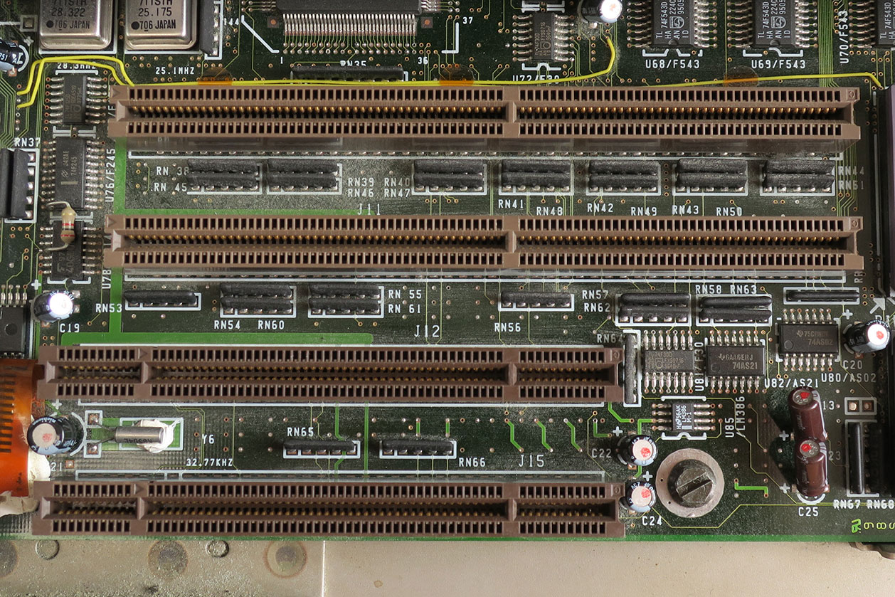
Five 16-bit and one 8-bit ISA slots on a motherboard: Miha Ulanov
For the 80286-based IBM PC-AT, an improved bus design that could transfer 16 bits of data at a time was announced. The 16-bit version of the ISA bus is sometimes known as the AT bus. (AT-Advanced Technology)
The improved AT bus also provided a total of 24 address lines, which allowed 16MB of memory to be addressed. The AT bus was backwards compatible with its 8-bit predecessor and allowed 8-bit cards to be used in 16-bit expansion slots.
8-Bit ISA card (XT-Bus)
16-Bit ISA (AT –Bus card)
8-bit data interface
16-bit data interface
4.77 MHZ bus
8-MHZ bus
62-pin connector
62-pin connector
36-pin AT extension connection
Comparison between 8-bit ISA and 16-bit ISA Bus (XT Bus vs AT Bus)
Problems with the ISA Design
The ISA design endured the PC market for quite a
while. However, it suffered from two major shortcomings. These are, lack of
speed and compatibility problems arising from card design.
Plug and Play Specifications
In 1993 the IEEE (Institute of Electrical and Electronics Engineers) standardized the Plug and Play (PnP) specifications. Some ISA cards and ISA buses that support plug-and-play became available in the market.
The PnP system allows devices to
automatically configure themselves.
MCA (Micro Channel Architecture) Computer Bus
This bus design was developed by
IBM as a replacement for ISA when they designed the PS/2 PC which was launched
in 1987.
The bus offered several technical improvements over the ISA bus. For instance, the MCA runs at a faster speed of 10MHz and can support either 16-bit or 32-bit data. It also supports bus mastering.
One advantage of MCA was that the plug-in cards were software configurable i.e. they required minimal intervention by the user when configuring. When a new expansion card was fitted and the PC powered up, it prompted the user to insert the machine’s reference diskette and the machine then automatically configured the new card’s resources and other parameters.
The MCA expansion bus did not support ISA cards and IBM decided to charge other manufacturers royalties for use of the technology. This made it unpopular and it is now obsolete technology.
Two 32-bit Micro Channel connectors and two 16-bit with Auxiliary Video Extension: Darklanlan
EISA (Extended Industry Standard Architecture)
EISA was developed by a group of manufacturers as an alternative to the MCA bus. It was designed to use a 32-bit data path and provided 32 address lines giving access to 4GB of memory. Like the MCA, EISA offered a disk-based setup for the cards, but it still ran at 8MHz for it to be compatible with ISA.
The EISA expansion slots are twice as deep as an ISA slot. If an ISA card is placed in an EISA slot it will use only the top row of connectors, whereas a full EISA card uses both rows.
EISA provided a much better performance than the ISA equivalent. Apart from being able to transfer 4 bytes of data simultaneously, it offers bus mastering; a technology that placed a mini-processor on each expansion card. These mini-processors controlled much of the transfer allowing the CPU to perform other tasks.
Extended Industry Standard Architecture: Wikimedia Commons
VESA Bus (Video Electronics Standards Association)
It is also known as the Local bus or the VESA-Local bus. VESA was invented to solve the problem of proprietary technology where different manufacturers were attempting to develop their buses. It was developed with the main aim of providing enhanced video performance on computers. It was thus aimed at standardizing PC’s video specifications.
The VL Computer bus provided a 32-bit data path and run at 25 or 33MHZ. It ran at the same clock frequency as the host CPU. But this became a problem as processor speeds increased. The faster the peripherals are required to run, the more expensive they are to manufacture.
It was difficult to implement the
VL-Bus on newer chips such as the 486s and the new Pentiums and so eventually
the VL-Bus was superseded by PCI.
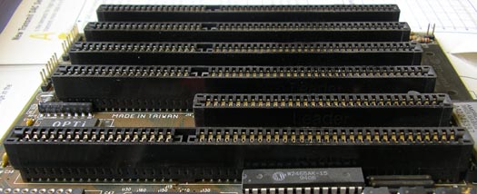
Computer motherboard with 7 ISA slots of various feature levels. Six are 16-bit ISA (longer – with middle black sections), and three additionally have a VLB slot (leftmost brown sections): Source
Features of The VESA Local Bus Card
32-bit interface
62/36-pin connector
90+20 pin VESA local bus extension
The VESA design was backwards compatible with the older ISA cards.
PCI (Peripheral Component Interconnect)
PCI brought about changes in the design of the bus and its communication with the processor bus. It was developed by Intel and launched as the expansion bus for the Pentium processor in 1993. It is a local bus like VESA meaning that it connects the CPU, memory, and peripherals to a wider, faster data pathway.
PCI supports both 32-bit and 64-bit data width; therefore it is compatible with 486s and Pentiums. The bus data width is equal to the processor, for instance, a 32-bit processor would have a 32-bit PCI bus and operate at 33MHz.
PCI was used in developing Plug and Play (PnP). All PCI cards support plug-and-play specifications. This means you plug a new card into the computer, power it on and it will “self-identify” and “self-specify” and start working without manual configuration using jumpers.
Unlike VESA, PCI supports bus mastering i.e. the bus has some processing capability and therefore the CPU spends less time processing data. Most PCI cards are designed for 5v, but there are also 3v and dual-voltage cards. Keying slots are used to differentiate 3v and 5v cards and slots to ensure that a 3v card is not slotted into a 5v socket and vice versa.
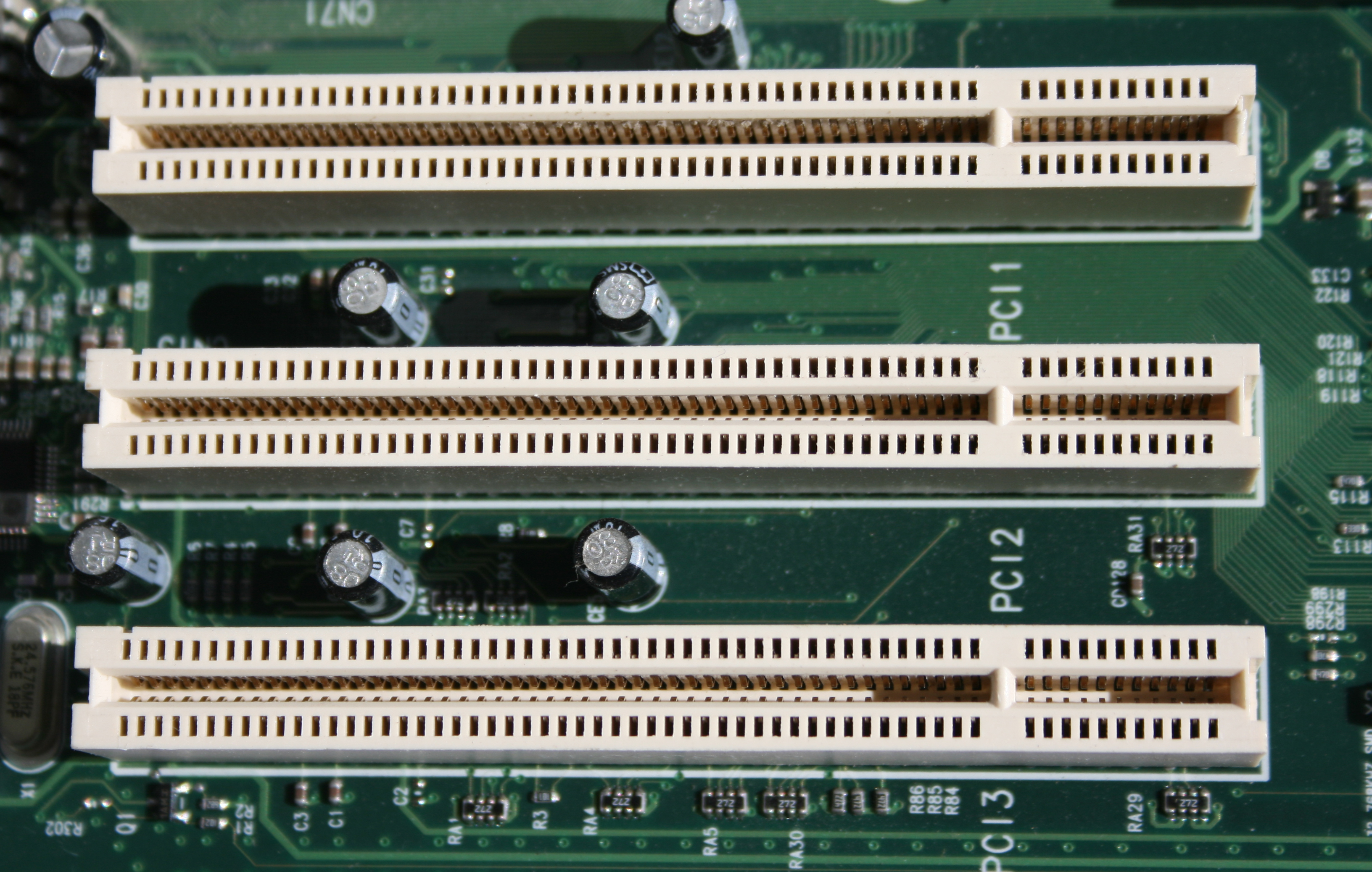
Three 32-bit PCI slots: I, Jonathan Zander [CC BY-SA 3.0 (http://creativecommons.org/licenses/by-sa/3.0/)]
The PCI Express Bus
The PCI Express bus comes in several
versions (1X, 2X, 4X, 8X, 12X, 16X and 32X), which provide throughputs of
between 250 Mb/s and 8 Gb/s, or close to 4 times the peak throughput of AGP 8X
ports. Because its manufacturing cost is that similar to that of the AGP port,
the PCI Express bus will progressively replace the former.
AGP (Accelerated Graphics Port) Computer Bus
The need for high-quality and very fast-performance of video on computers led to the development of the Accelerated Graphics Port (AGP). The AGP port is connected to the CPU and operates at the speed of the processor bus. This means that video information can be sent more quickly to the card for processing.
The AGP uses the main PC memory
to hold 3D images. In effect, this gives the AGP video card an unlimited amount
of video memory. To speed up the data transfer, Intel designed the port as a
direct path to the PC’s main memory.
The data transfer rate ranges from 264 Mbps to 528mbpn, 800 Mbps up to 1.5 Gbps.
AGP (Accelerated Graphics Port)
PCMCIA (PC Card)
The Personal Computer Memory Card
Industry Association was founded to provide a standard bus for laptop
computers.
PCMCIA is an organization consisting of some 500 companies that have developed a standard for small, credit card-sized devices, called PC Cards. Originally it was designed for adding memory to portable computers. The PCMCIA standard has been expanded several times and is now suitable for many types of devices. There are three types of PCMCIA cards. All three have the same rectangular size (85.6 by 54 millimetres), but different widths.
Type I cards can be up to 3.3 mm thick and are used primarily for adding additional ROM or RAM to a computer.
Type II cards can be up to 5.5 mm thick. These cards are often used for modem and fax modem cards.
Type III cards can be up to 10.5 mm thick, which is sufficiently large for portable disk drives.
SCSI (Small Computer System Interface)
SCSI (sku´zē) is a parallel interface standard used by Apple Macintosh computers, PCs, and many UNIX systems for attaching peripheral devices to computers. Nearly all Apple Macintosh computers, excluding only the earliest Macs and the recent iMac, come with a SCSI port for attaching devices such as disk drives and printers.
SCSI interfaces provide faster data transmission rates (up to 80 megabytes per second) than standard serial and parallel ports. In addition, you can attach many devices to a single SCSI port, so that SCSI is an I/O bus rather than simply an interface.
USB (Universal Serial Bus)
This is among the latest addition to the computer bus collection. The universal serial bus connects external peripherals such as a mouse, keyboards, joysticks, printers, flash drives, scanners, and digital cameras to the computer. A single USB port can connect up to 127 peripheral devices. This computer bus also supports Plug-and-Play installation and hot plugging.
Various USB Data Transfer Rates
USB 1.0
A data rate of 1.5 Mbits per second (Mbps)
USB 2.0
High Speed
Throughput up to 35 MB per second (280 Mbit per second)
Support battery charging
USB 3.0
Very High Speed
10 times faster than USB 2.0
Supports data rate up to 512 MB per second (4 Gbit per second)
Uses two unidirectional data paths one to receive and the other to transmit data
USB 3.1
USB 3.1 Gen 1 supports speeds of up to 5Gbit/s,
While USB 3.1 Gen 2 supports speeds of up to 10Gbit/s.
USB 3.1 Gen 1 Type-C Male to Type-A Male Cable
FireWire or IEEE 1394
This is a very fast external computer bus standard that supports data transfer rates of up to 400Mbps (in 1394a) and 800Mbps (in 1394b). Products supporting the 1394 standard go under different names, depending on the company.
Apple, which originally developed the technology, uses the trademarked name FireWire. Other companies use other names, such as i.link and Lynx, to describe their 1394 products.
A single 1394 port can connect up to 63 external devices. In addition to its high speed, 1394 also supports isochronousdata – delivering data at a guaranteed rate. This makes it ideal for devices that need to transfer high levels of data in real time, such as video devices.
Although extremely fast and flexible, 1394 is also expensive. Like USB, 1394 supports both Plug-and-Play and hot plugging and also provides power to peripheral devices.
Computer Bus | What Is A Computer Bus ? | Computer Bus Types